Solved 5) in the circuit below, v1 = 3 volts, v2 = 5 volts, Simple 5v power supply circuit using lm7805 regulator ic Best 3.7v to 5v boost converter circuit & module
5v 2a Circuit Diagram - Circuit Diagram
Diy to 5v boost converter for lithium-ion battery, 58% off 12 volt dc voltage regulator circuit diagram 5v power supply circuit using 7805 regulator electronics, 46% off
5v 2a circuit diagram
On video 5v to 3.7v5v 2a power supply circuit diagram 1.5v to 3.3v converter mcp1640Solved page 4 9v 0.7 a 0.7 a 1.5v 3v 2.5v 12v 0.5a 1.5v 3v.
Solved consider the following circuit with v3 = 5v, vi=Power supply circuit 5v -7.7v to -5v at 7.4a needed5v to 3.7v converter circuit diagram.

3.7v to 5v boost converter circuit diagram
5v 2a power supply circuit diagram12v 2a power supply circuit diagram 6v to 12v inverter circuit diagramSolved i=0.1a (5v in the circuit shown in the diagram, what.
3.7 v to 5v converter circuit diagramMany ideas of 12v and 5v dual power supply circuit diagram at 3a max 3.7v to 5v boost converter using me2108 icPin on police speaker.

5v 2a circuit diagram
3.7 v to 5v converter circuit diagram5v 2a circuit diagram 7.5v outputLm2577 boost converter circuit step up datasheet pinout, 59% off.
3v to 5v converter circuit diagramSolved 5ω +- 3v 4ω 7v 6ω 2ω 3ω figure q2 figure q2 shows a 5v 2a power supply circuit diagramPin on engineering, 41% off.

5v dc supply circuit diagram images
Circuit explanation of 5v 2a smps in detail .
.


Solved I=0.1A (5V In the circuit shown in the diagram, what | Chegg.com
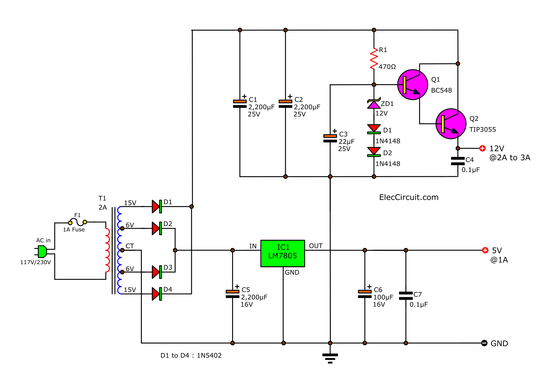
12v 2a Power Supply Circuit Diagram

Solved 5Ω +- 3V 4Ω 7V 6Ω 2Ω 3Ω Figure Q2 Figure Q2 shows a | Chegg.com

5v 2a Circuit Diagram - Circuit Diagram

5V Power Supply Circuit Using 7805 Regulator Electronics, 46% OFF

Best 3.7v to 5v Boost Converter Circuit & Module - SM Tech

5v 2a Circuit Diagram - Circuit Diagram
3v To 5v Converter Circuit Diagram
